SLS 3d printing
SELECTIVE LASER SINTERING
SUBMIT YOUR FILE FOR A FREE QUOTE!
How the SLS Process Works
-
Powder Layering
A thin, uniform layer of thermoplastic powder is spread across the build platform. -
Laser Sintering
A high-precision laser scans and selectively fuses powder particles in designated areas, solidifying one cross-section of the part. -
Layer-by-Layer Construction
The build platform lowers slightly, and a fresh layer of powder is applied. The laser continues to fuse each new layer, bonding it to the one below until the full part is formed. -
Self-Supporting Environment
Loose powder surrounds the printed geometry, naturally supporting overhangs and complex features without the need for additional support structures. -
Post-Processing
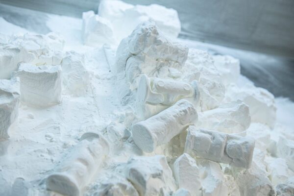
After printing, excess powder is removed through blasting or vacuuming. Optional finishing steps such as vapor smoothing, dyeing, or coating can be applied to enhance the part’s appearance and performance.
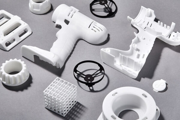
This high-precision, tool-free process makes SLS ideal for functional prototypes, production parts, and complex geometries, ensuring high strength, durability, and design freedom.
Key Advantages of SLS 3D Printing
-
High Resolution – Reproduces fine details down to 0.002″, ideal for complex and intricate components
-
Fast Turnaround – Efficiently supports batch production with minimal lead time
-
Support-Free Printing – Prints complex geometries without the need for supports, reducing post-processing time
-
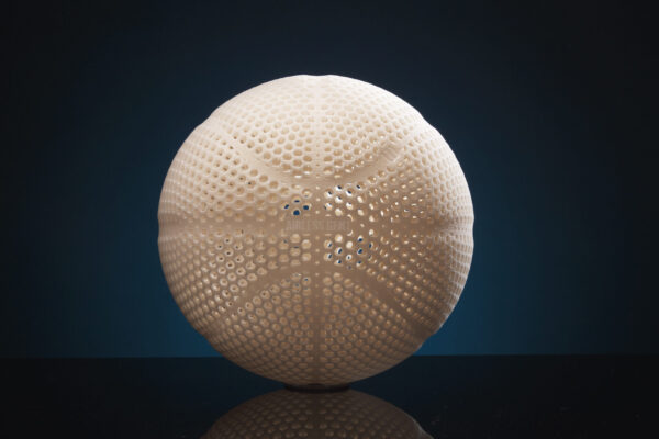
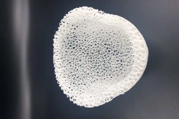
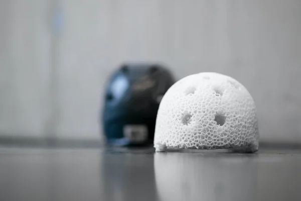
Design Freedom – Enables advanced structures like lattices, interlocks, and organic forms
-
Optimized Build Volume – Full chamber utilization allows dense part nesting, lowering per-part costs
SLS Applications
-
Functional Prototypes – Delivers robust, testable parts with real-use mechanical performance
-
Production-Grade Products – Seamlessly transitions from prototype to end-use manufacturing
-
Flexible Volume Output – Scalable from low-run validation parts to full-volume production
-
Durable End-Use Components – Produces engineering-grade, wear-resistant final parts
SUBMIT YOUR FILE FOR A FREE QUOTE!
SLS 3D Printing Materials
SLS is compatible with a variety of high-performance materials, including:
- Nylon 11 (PA1100) – High ductility, impact resistance, and flexibility
- Nylon 12 (PA2200) – Excellent strength, durability, and chemical resistance
- TPU 1301 – Flexible, rubber-like material for soft-touch applications
SLS Design Guidlines and Quality
With our ISO 9001-certified quality management system, SNL Creative delivers best-in-class SLS parts that meet stringent industry standards. Our processes ensure consistent accuracy, material integrity, and repeatability, making us the trusted partner for industrial-grade additive manufacturing.
| Design Feature | Guideline | Description |
| Minimum Wall Thickness (Supported) | 0.8 mm – 1.0 mm | Walls supported on at least two sides must be thick enough to ensure structural stability and avoid deformation during sintering. |
| Minimum Wall Thickness (Unsupported) | 1.5 mm | Unsupported walls require greater thickness to resist warping and breakage due to thermal stress. |
| Minimum Pin Diameter | 0.8 mm | Pins or thin freestanding features must meet this diameter to maintain integrity during sintering and powder removal. |
| Engraved Details | Min width/depth: 0.5 mm | Recessed features must meet minimum size to avoid filling with powder and losing definition. |
| Embossed Details | Min width/depth: 0.5 mm (Text: 1.5 mm flat / 2 mm vertical) | Raised features resolve better but must be thick enough to maintain detail and legibility. |
| Minimum Text Size | 14 pt | Use sans-serif fonts with 0.5 mm line thickness for clear, legible text on all orientations. |
| Minimum Clearance (Moving Parts) | 0.5 mm | Gap needed between parts to avoid sintering together and ensure functional movement. |
| Minimum Press Fit Offset | 0.1 mm | Ensures tight yet functional fit for parts that press together without fasteners. |
| Hinges & Linkages Clearance | 0.6 mm | Minimum spacing between moving parts like joints or chains to allow free movement. |
| Minimum Hole Diameter | 0.5 – 0.7 mm depending on wall thickness | Ensure proper powder removal and functional openings by sizing holes based on surrounding wall thickness. |
| Minimum Gap | 0.5 – 0.7 mm depending on wall thickness | Gaps between features should align with wall strength to prevent fusion or clogging. |
| Minimum Escape Hole | 4 mm (2 mm x2 for larger parts) | Facilitates removal of unsintered powder from internal cavities and channels. |
| Tolerances (PA 12) | ±0.25%, minimum ±0.25 mm | General dimensional accuracy for most rigid parts; warping may occur on large flat surfaces. |
| Tolerances (TPU) | XY: ±0.50 mm, Z: ±1.50 mm | More flexible material requires broader tolerances due to higher shrinkage and deformation potential. |
| Layer Height | 60 – 120 µm | Smaller layer heights yield finer resolution but increase print time; standard is 100 µm. |
| Maximum Build Size | 340 x 340 x 600 mm | Defines the largest single part that can be printed in one build on EOS P396. |
| Surface Finish | Uniform matte | Parts have a fine, powdery texture; suitable for functional use and enhanced with post-processing. |
| Machinability | Post-machining supported | Parts can be milled or drilled after printing for improved precision or feature definition. |
| Threads | M6 or larger with 0.5 mm offset | Printed threads require sufficient size and offset; for frequent use, consider heat-set or machined inserts. |
| Post-Processing Options | Bead blasting, vapor smoothing, dyeing, coating | Enhances aesthetic, mechanical, and environmental performance of finished parts. |
