FDM
Fused Deposition Modeling
SUBMIT YOUR FILE FOR A FREE QUOTE!
Fused Deposition Modelling (FDM)
from Stratasys works with production-grade thermoplastics to build strong, durable and dimensionally stable parts with the best accuracy and repeatability of any 3D printing technology.
In FDM, melted thermoplastic is extruded onto a build platform, fusing layer on top of layer, until a 3D shape takes form. FDM filaments range from biodegradable PLA, ABS, PEEK and Many other thermoplastics
Traditional filaments continue to evolve with integrated features such as acid and chemical resistance, low friction, and high strength. Newer FDM filaments contain chopped fiber blends such as polycarbonate and carbon fiber to produce strong, lightweight, and dimensionally stable parts. FDM 3D prints can range from small replacement parts for classic cars to production tooling and fixtures for aerospace companies, making it the stronger choice for objects that require mechanical function and performance.
For demanding applications, rely on our large platform FDM from Stratasys. Print with advanced materials that meet tough certification standards.
FDM BENEFITS
- High Resolution
- High Speed – in some cases same day turnaround
- Fine detail and smooth surfaces directly off machine
- Complex geometries and cavities
- High performance material properties of heat and UV resistance.
- Medical and food grade material availability
- Soluble material for sacrificial composite tooling
- Functional Prototyping and production
APPLICATIONS USING FDM 3D PRINTING
- Prototyping and Presentation models
- Prosthetics
- End-use aerospace, automotive, manufacturing and medical applications
- Models for architecture and medical use
- Props for the entertainment industry
- Production tooling

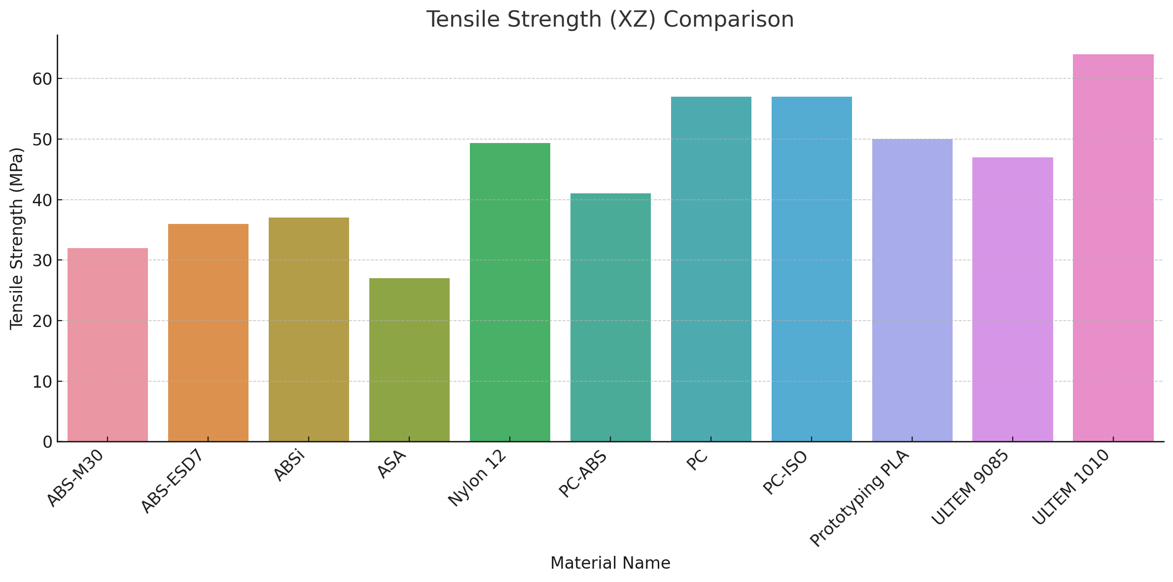
| Material Name | Color(s) | Tensile Strength Yield (XZ MPa) | Tensile Strength Yield (ZX MPa) | Elongation at Break (XZ%) | Elongation at Break (ZX%) | HDT @ 66 psi (°C) |
| ABS-M30 | Black, Blue, Dark Grey, Ivory, Red, White | 32 | 28 | 7 | 2 | 96 |
| ABS-ESD7 | Black | 36 | 36 | 3 | 3 | 96 |
| ABSi | Translucent Natural, Amber, Red | 37 | 37 | 4.4 | 4.4 | 86 |
| ASA | Multiple Colors | 27 | 27 | 9 | 3 | 98 |
| Nylon 12 | Black | 49.3 | 41.8 | 30 | 6.5 | 91.9 |
| PC-ABS | Black | 41 | 41 | 6 | 6 | 110 |
| PC | White | 57 | 42 | 4.8 | 2.5 | 138 |
| PC-ISO | Translucent Natural, White | 57 | 57 | 4 | 4 | 133 |
| Prototyping PLA | Black, Blue, Red, White | 50 | 37 | 2.9 | 1.9 | 55 |
| ULTEM 9085 | Black, Tan | 47 | 33 | 5.8 | 2.2 | 153 |
| ULTEM 1010 | Amber (Natural) | 64 | 41 | 3.3 | 2 | 216 |
| Nylon 12CF | Black | 76 | 43 | 1.9 | 1.4 | 143 |
Material Data Sheets
Click on materials for mechanical specs


| Design Element | Recommendation | Notes |
|---|---|---|
| Wall Thickness | Minimum: 1.2 – 1.5 mm (0.047″ – 0.06″) | At least 2x filament width (0.254 mm typical); thin walls can cause poor resolution |
| Holes | Minimum: 1.0 mm (0.04″) diameter | Best when oriented parallel to XY plane; post-processing drilling for high precision |
| Text & Small Features | Minimum height & thickness: 1.2 – 1.5 mm (0.047″ – 0.06″) | Avoid fine or condensed fonts; orient parallel to XY for best legibility |
| Gaps | Minimum: 5 mm (0.2″) gap width | To ensure clean support removal; orient openings to XY plane for clarity |
| Tabs | Maximize size; orient parallel to XY plane | Use replaceable tab design if possible |
| Fillets | Add fillets wherever possible to reduce stress | Fillets improve strength and reduce need for support on overhangs |
| Ribs | Minimum: 1.5 mm (0.06″) thick | Adds strength; must meet wall thickness minimum |
| Overhangs | Maximum angle: 45° from vertical before support is required | Gradual slopes preferred |
| Bridges | Max unsupported span: 5 mm | Larger spans may sag or require support |
| Infill Options | – Ultralight (single cross-hatch) – Light (double cross-hatch) – Solid (fully dense) |
Choose based on strength vs. cost balance |
| Part Orientation | Orient XY plane parallel to key features (holes, text, tabs) | Improves accuracy, strength, and finish |
| Surface Finish | Expect layer lines, especially on curved or angled surfaces | Printing curves aligned to the build plane improves surface quality |
| Tolerances | – XY: ±0.004” or ±0.002” per inch – Z: ±0.010” or ±0.002” per inch |
Applies unless otherwise specified |
| Build Volume | Up to 24” x 36” x 36” | Check material-specific limits |
| Materials Available | ABS, ASA, PC, Nylon, Ultem, PPSF | Varies by application: strength, heat resistance, sterilization, etc. |